Build Process
Follow the journey of creating our LED Resin Cube from concept to completion
Project Documentation
Access our detailed project documentation below:
The Development Journey
Our LED Resin Cube went through several phases of development, from initial concept sketches to the final product. Below you'll find documentation of each major step in our build process.
Step 1: Initial Design
Initial design sketch of the cube structure
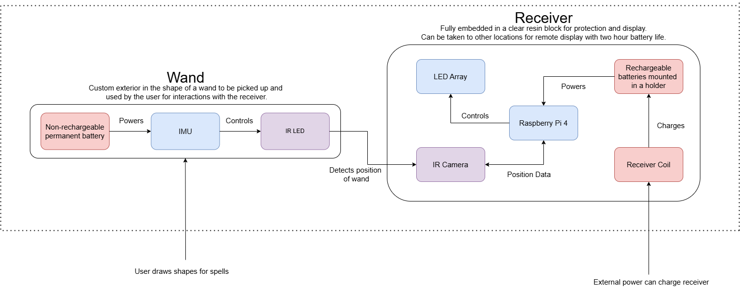
The first step in the build process was to decide the components in the receiver and wand as well as how they would communicate. Our requirements called for the receiver to be encased in resin and for LEDs to light up in response to different predefined user gestures.
We decided upon using a Raspberry Pi 4b as the processing unit. This was determined to be necessary over other microcontrollers such as ESP32s because of the processing power required for gesture/image recognition software that we planned to use, as well as its ability to easily interface with high-resolution cameras. The wand was determined to emit an IR signal for tracking by the camera in the receiver as well as include an inertial measurement unit for more complex gestures. Wireless charging for the receiver was chosen to prevent the need for cables poking out of the cube.
Step 2: Initial Electronics Testing

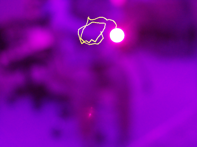
The first IR test was done with the camera and an IR filter in front of it. The IR LED is attached to a battery pack, forming our first prototype wand. The LED is clearly visible and software was written to trace the path of the wand, which can be seen here. Eventually we would use this basic tracing function to be able to recognize different gestures made by the user.
The most challenging part of this was ensuring that the camera remained solely focused on the IR LED and would not attempt to track other features in the environment. Although we have mostly been able to mitigate this as an issue, it can sometimes occur under unique lighting circumstances.
Step 3: Initial Resin Testing
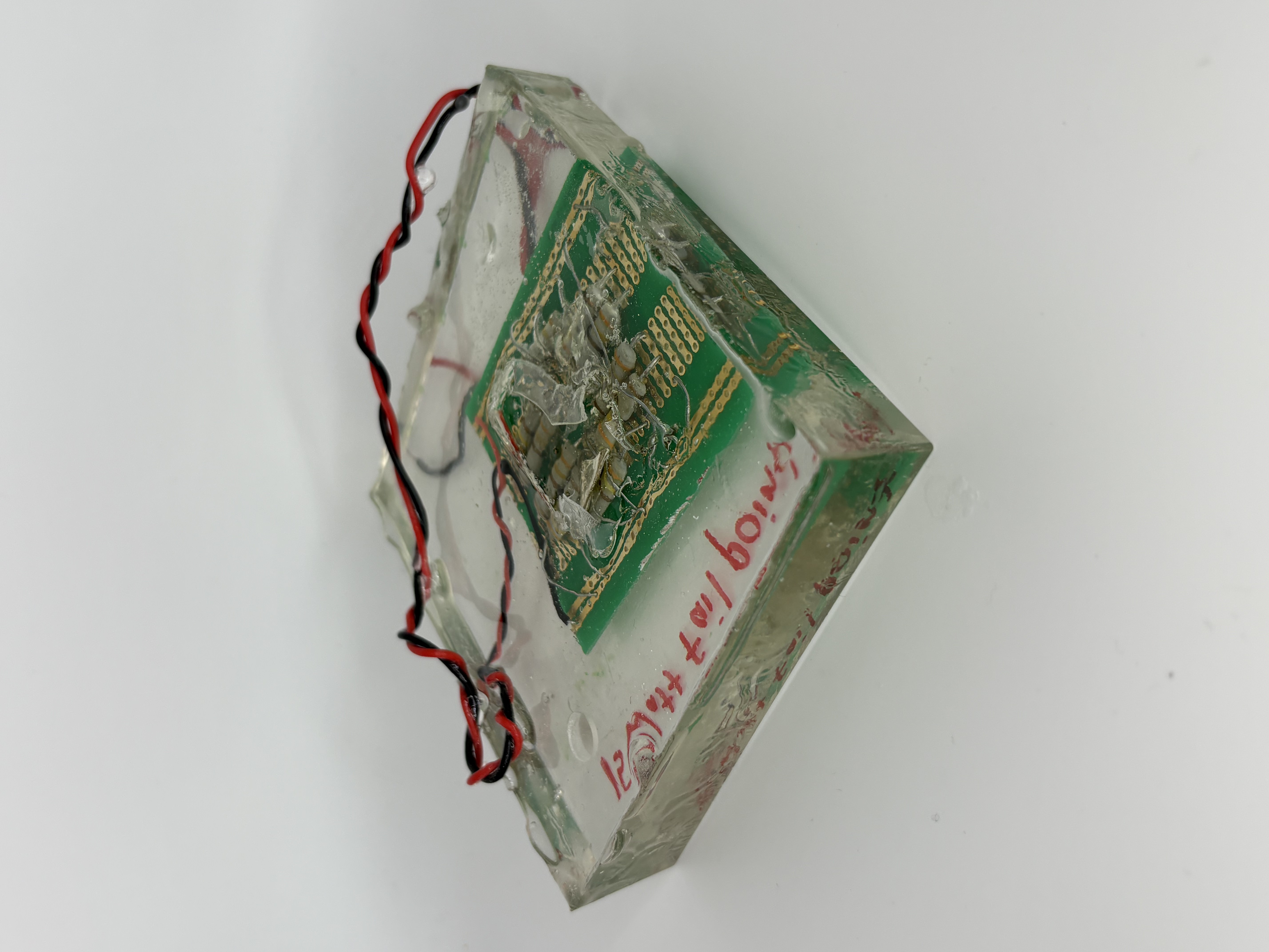
In the initial design and testing phase, the team was worried about how heat dissapation would be affected by the electronics being embedded in resin. In order to determine the thermal properties of the resin, we tested the power limits of it. Using a 1Ω equivalent ciruit, the resin ended up cracking at 15W of power. This set the upper threshold for power consumption of our system to build around.
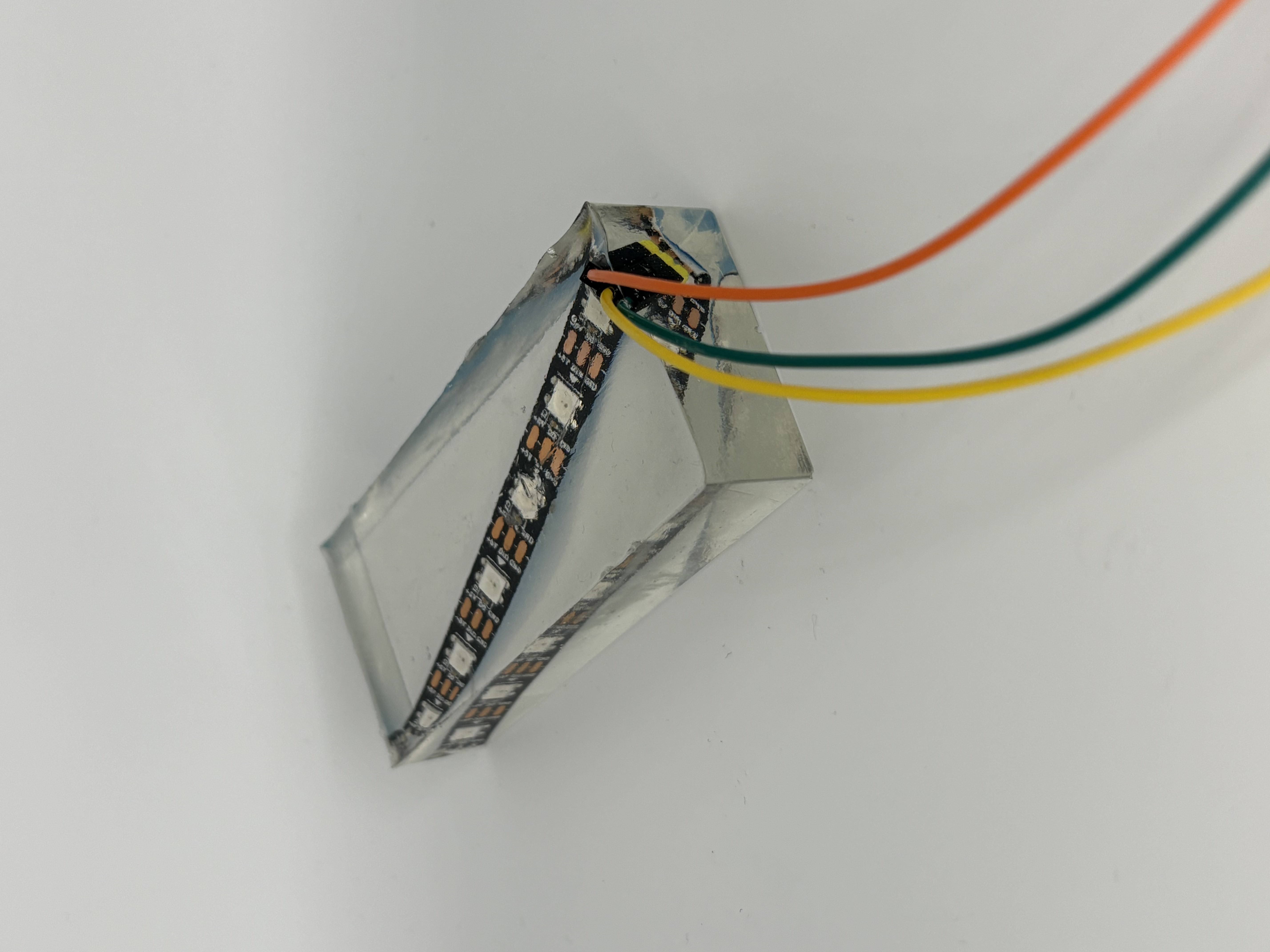
All components that would be placed in the resin cube were individually tested in resin before the first prototype cube was assembled. The LED strip seen above was one of the components. Although we assumed certain components such as the LEDs would behave normally, we wanted to eliminate risks that would otherwise be hard to find when the entire system was assembled.
Step 4: First Resin Cubes
First cube
Molds
The first resin cube can be seen on the left. It was set in a 3D printed box as its mold and have few functional components. The main goal of this cube was to analyze the full setting process as well as peak temperature during the set. The ratio of epoxy resin to the hardening agent is crucial. We had not measured them precisely enough, resulting in the resin taking multiple days to fully set and a sticky texture on the outside.
The cube's maximum temperature was 70°C and was affected by the amount of resin setting at a given time. Additionally, the 3D printed cube was not an optimal mold as the cube was extremely difficult to remove. As a result, we began to create our own silicone molds that could be shaped to specific sizes and were far easier to remove the cubes from. One of the molds can be seen on the right.
Step 5: Resin Cube Iterations
First cube
Molds
The second resin cube developed can be seen on the left. It included a functional Raspberry Pi 4b and LED PCB on the front side. The Raspberry Pi and LEDs were able to light up through an external power from outside the cube. However, the elements in the cube would shift while it was setting, resulting in a messy look inside of the resin. The resin was also not as clear as we wanted it to be.
We preformed multiple tests to determine the cause of the resin not setting in a clear manner and concluded that it was due to air bubbles appearing when it was stirred too quickly. Additionally, a 3D printed stand was printed for the components to rest on so that they do not move when the resin is being set. The first stand prototype can be see on the right.
Step 6: Refinement
cube 2
final cube
The cube seen on the left was the next iteration of the cube that included significant improvements. The battery and charging system worked inside the cube and the Raspberry Pi's camera was fully functional, albeit slightly distorted.
The cube on the right is considered out minimum viable product. The resin has been properly set and the electronics are fully functional. Although the cube works, the gesture recognition was not fully accurate due to the positioning of the camera being slightly further back in the cube and some air bubbles in front of it distorting the tracking capabilities.
Step 7: Wand Development
cube 2
final cube
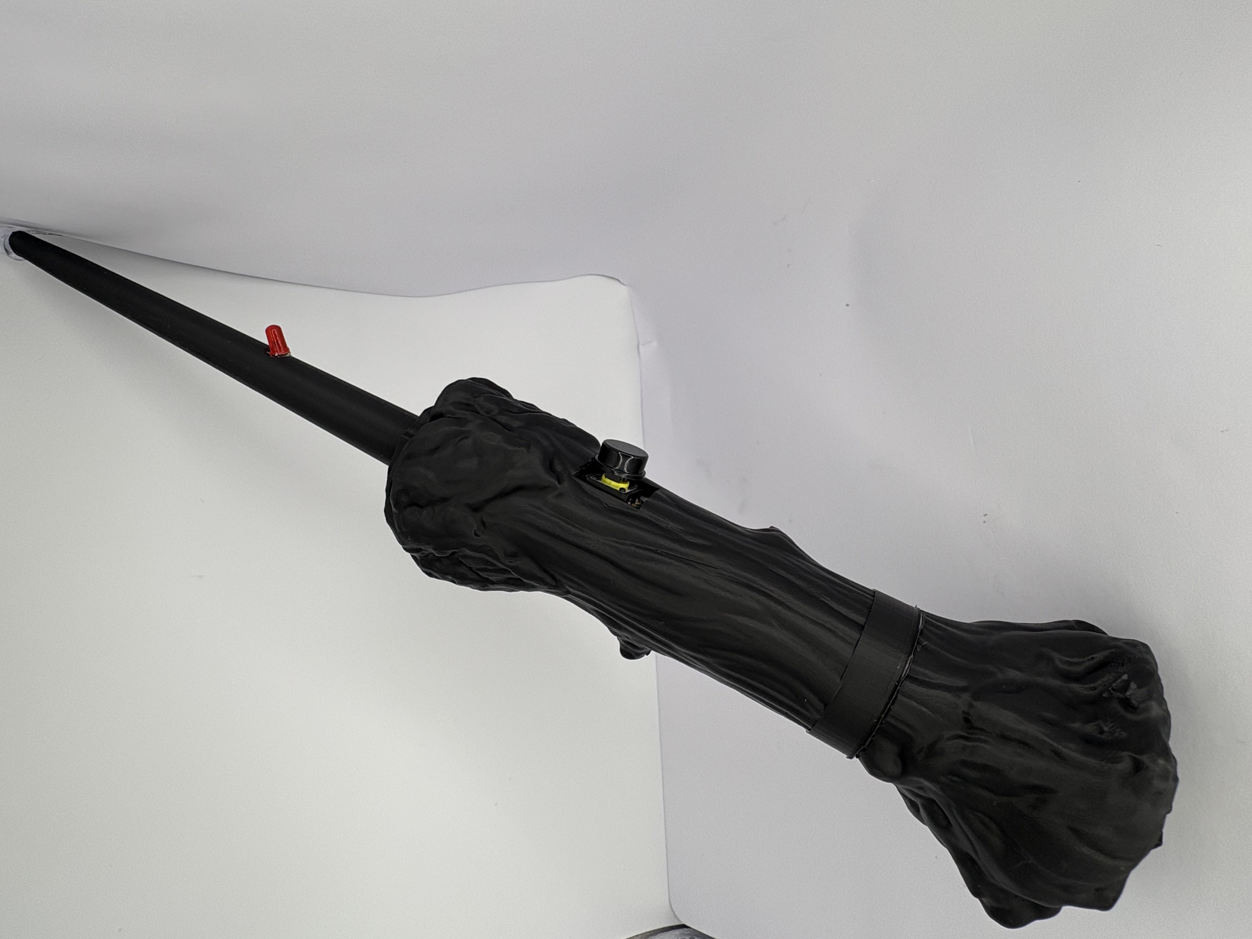
The wand was more difficult to develop than we had initially imagined it to be. The circuit is simple, with only a battery, a button to turn it on, and an IR LED. The team first considered making it out of resin, like the cube, but encountered difficulties with this approach.
By encasing it in resin, it was difficult to get the components set correctly and made it difficult to have a button to turn on the wand. The button also frequently got stuck, rendering it unusable. The team switched to 3D printed cases for the wands, with the electronics mounted inside. This proved more reliable and easier to produce, making it the optimal solution for us.
Final Result
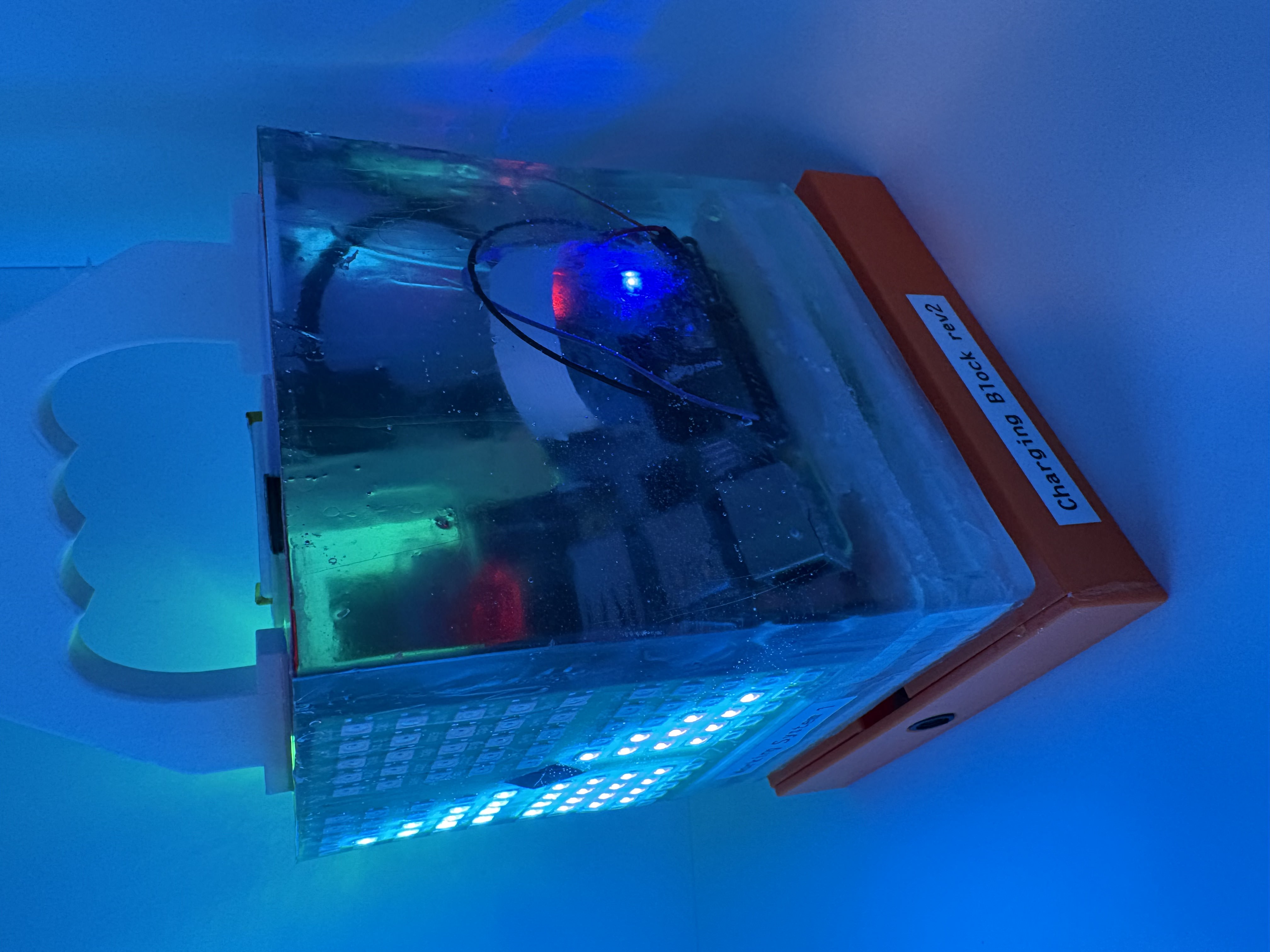
The completed LED Resin Cube
The cube displaying a light pattern
After seven months of development, the system was complete and working. The cube is powered by a rechargable battery by the wireless charging coil in the base of the cube. The orange base is the other part of the wireless charger that the cube sits on to charge. An HDMI port is available on the top of the cube, although it is not needed for operation. An LED indicator on the side of the cube displays the charge level. The Raspberry Pi boots on startup and begins running the software for the wand to communicate with. The vibrant 10x10 smart LED display on the front shows different preprogrammed patterns when the device predicts the gesture with the user waves. The wand has a removable base to switch the battery from and a red LED that turns on with the IR LED when the button is pressed, allowing the user to know if the battery is dead and when the wand is turned on.
Overall, we are extremely satisfied with the final result and proud of the obstacles that we overcame to get here. The biggest challenges that the team overcame throughout the development process were overheating issues from the resin, difficulties implementing the IR gesture recognition software, and distortions to the camera due to small air bubbles in front of it in the resin. Major takeaways that we learned include the importance of software testing and individual component tests. Users familiar with how our software worked understood how to correctly use the wand with it, but new users often struggled and were able to help use spot blindspots in our code that we would not have otherwise noticed. Additionally, the irreversability of resin setting meant that it was extremely important to test the individual components in them before putting the full hardware package in resin. Finally, some future improvements that we would make include changing the IR to be pulse width modulated, so that software only tracks its specific frequency. We would also increase the amount of features we have for user feedback such as adding an audio response and showing the user's motion on the LED array.