Overview

This comprehensive lesson introduces students to fundamental electrical circuitry concepts through structured engagement with an interactive circuit cube. The hands-on approach is designed to reinforce theoretical concepts with practical application, addressing key learning standards in physical sciences.

The interactive cube serves as both demonstration tool and student workstation, allowing for direct observation of electrical principles including closed circuits, conductivity, resistance, and component functions. Students will progress through guided activities that build technical vocabulary and conceptual understanding while developing troubleshooting skills.

This lesson supports differentiated learning by providing tactile experiences alongside visual demonstration, making abstract electrical concepts concrete and observable. The cube's design facilitates both individual exploration and collaborative problem-solving, allowing educators to assess student comprehension throughout the learning process.

By lesson completion, students will demonstrate measurable understanding of circuit fundamentals and component relationships, establishing foundational knowledge for more advanced electrical engineering concepts in future lessons.

Lesson Details

Lesson 1: Build a Simple LED Circuit

This lesson introduces students to basic electronics by building a simple LED circuit powered by a coin cell battery.

Objectives

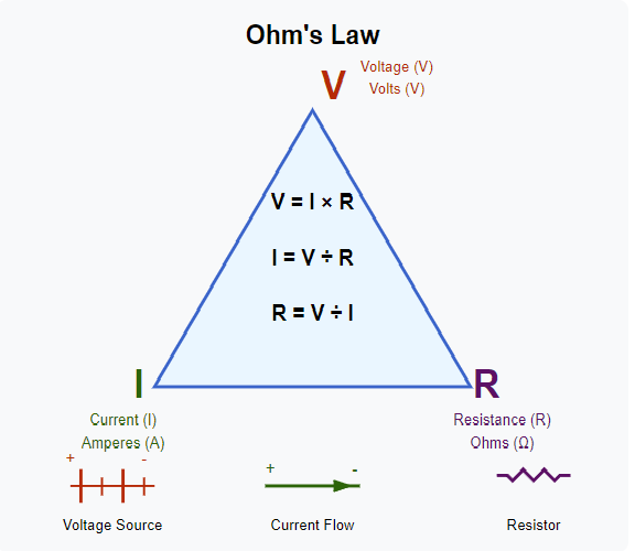
  • Understand current flow and polarity in a circuit.
  • Identify LEDs, resistors, and batteries.
  • Safely build a basic circuit using simple components.

Materials

  • 1x Breadboard (or cardboard + copper tape)
  • 1x Coin cell battery (CR2032) or AA battery pack
  • 1x LED (any color)
  • 1x 330Ω resistor
  • Tape or clips for temporary connections

Instructions

  1. Insert the LED into the breadboard. Identify the long leg (anode) and short leg (cathode).
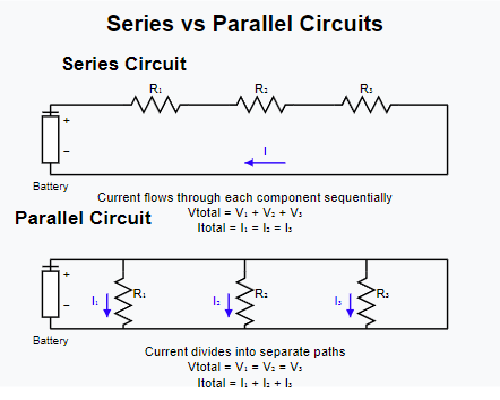
  2. Connect the resistor in series with the LED’s anode.
  3. Attach the coin cell battery to power the circuit (positive to the resistor, negative to the cathode).
  4. Observe the LED lighting up.

Visual Guide

Simple LED Circuit Diagram

Downloadable Worksheets

Lesson 2: Understanding Circuit Behavior

Objectives

  • Learn the relationship between voltage, current, and resistance.
  • Apply Ohm’s Law to simple series circuits.
  • Use a multimeter to measure voltage and resistance.

Materials

  • 1x Breadboard
  • 1x Coin cell or AA battery
  • 1x LED
  • 2x Resistors (e.g. 330Ω and 1kΩ)
  • 1x Multimeter (if available)

Concepts Covered

  • Ohm’s Law: V = IR
  • Series resistance: total resistance = sum of resistors
  • How to predict current flow through a simple circuit

Hands-On Activity

  1. Build a circuit with one resistor and LED in series.
  2. Use Ohm’s Law to calculate expected current (I = V/R).
  3. Measure the actual voltage drop across components with a multimeter.
  4. Swap in a second resistor and re-analyze the circuit.

Visual Guide

Ohm's Law Diagram

Downloadable Worksheet

Lesson 3: Exploring Real-World Electronics & Advanced Circuit Concepts

Objectives

  • Understand voltage division and the impact of resistor configurations.
  • Compare and contrast series and parallel circuits.
  • Read and interpret simple schematic diagrams.
  • Explore how microcontrollers (e.g., Arduino) can control components like LEDs.

Materials

  • 1x Breadboard
  • 1x Coin cell or AA battery pack
  • 3x LEDs
  • Assorted resistors (330Ω, 1kΩ, etc.)
  • Jumper wires
  • Optional: Arduino Uno (or similar) + USB cable
  • Optional: Multimeter

Key Concepts

  • Voltage division across resistors
  • Differences in behavior between series and parallel configurations
  • Introduction to circuit schematics and symbols
  • Digital control with microcontrollers (digitalWrite, pins, HIGH/LOW)

Hands-On Activity

  1. Build a simple parallel LED circuit. Observe brightness compared to a series circuit.
  2. Measure voltage across each LED using a multimeter.
  3. If using an Arduino: upload a simple sketch to blink LEDs using digital pins.
  4. Draw a schematic of your circuit using symbols for LEDs, resistors, and power.

Extensions

  • Try adding a pushbutton to control the LED circuit.
  • Experiment with different resistor values to see how they affect current and brightness.
  • Code a blinking pattern or a basic light sweep with the Arduino.

Real-World Connections

These concepts underpin systems from wearable electronics to home automation. Understanding how to build and analyze these simple circuits sets the stage for exploring microcontrollers, sensors, and full embedded systems used in real engineering projects.

Visual Guide

Series vs. Parallel Circuit Diagram

Downloadable Worksheet