Circuit Design
Exploring the electronics that power our LED Resin Cube
Electronics Overview
The resin block relies on a Raspberry Pi 4b to interpret IR signals and control the smart LEDs. A Raspberry Pi High Quality Camera module is used to look at the IR signal from the wand. It has native support from the Raspberry Pi and is capable of detecting IR light. A custom PCB was designed to hold and power the 100 smart LEDs. The circuit is powered by a 5000mAh rechargable battery wirelessly charged. A custom LED charge level indicator is also included to display the battery charge.
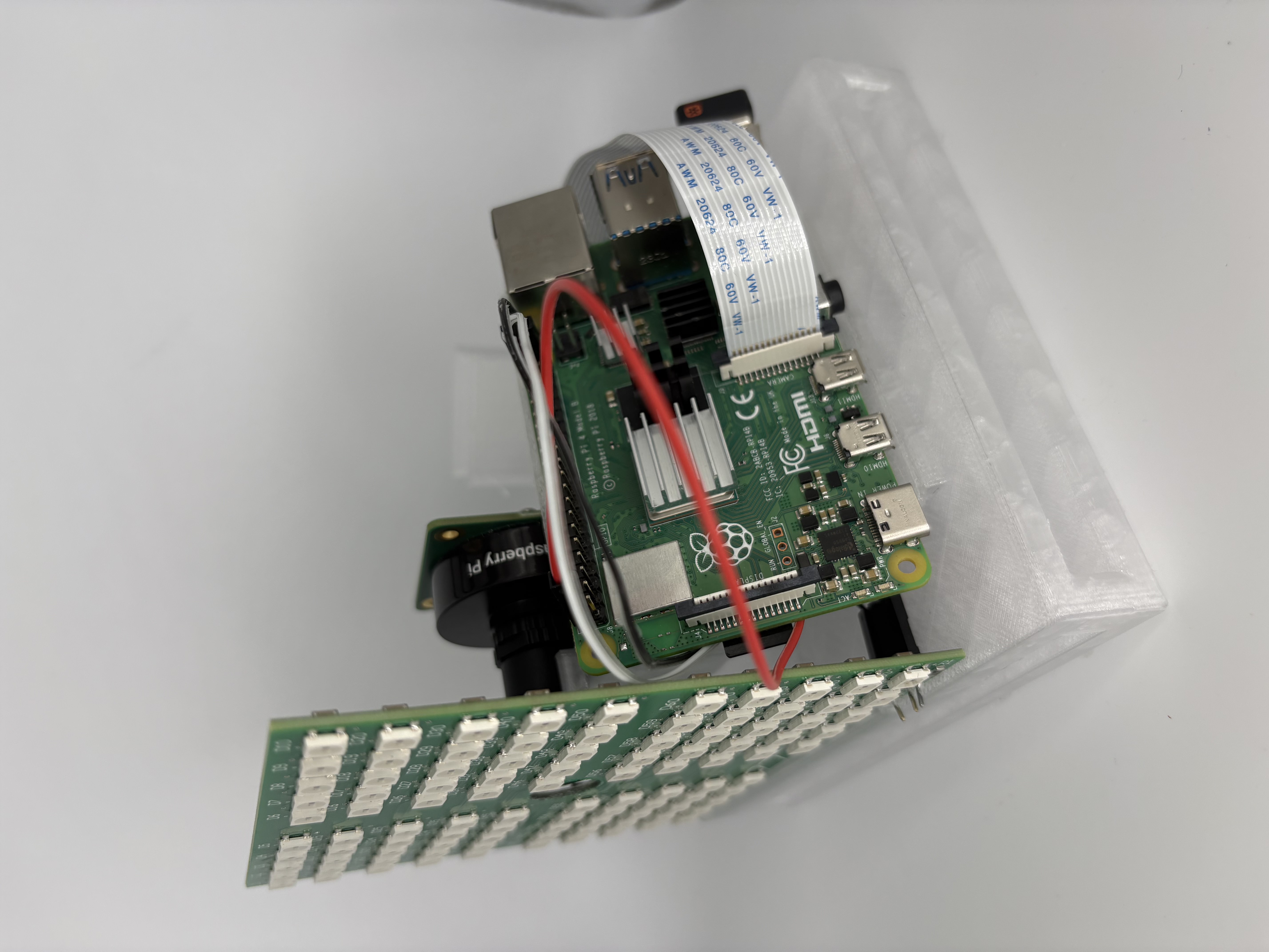
Raspberry Pi, Camera, and LED PCB
The Raspberry Pi can be seen here connected to the camera and the LED PCB. The LEDs are controlled by the 5V & Ground Pins on the Pi, and data is provided to them through a GPIO pin.
The Raspberry Pi's ARM Cortex A-72 processor is sufficient for the computer vision algorithms running. The camera is high enough resolution for proper tracking and is connected to the Pi with a ribbon cable. The Pi is able to be communicated with via SSH, even when it is in the resin. Shell scripting in the Pi ensures that the program runs on startup without external user assistance.
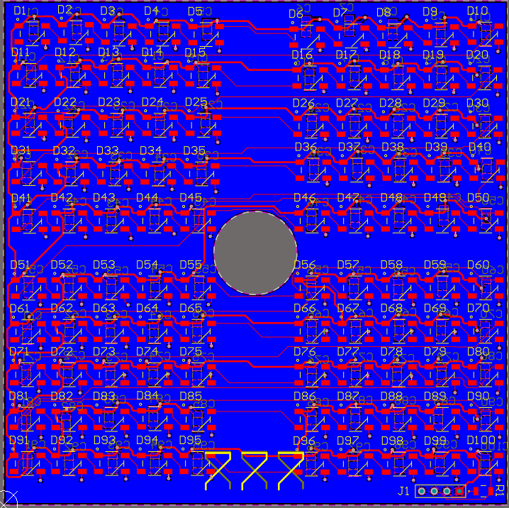
LED Matrix
The LED matrix provides the visual feedback for the project. The original design was a 6x6 matrix, however our power budget allowed for the increase to 10x10.
Size and spacing were a challenge with this circuit due to the amount of LEDs required. The middle was left empty to allow for a hole through the PCB. The IR camera is positioned behind it and looks through the hole. This allows us to reduce the size of the cube and dedicates more space on the front to be taken up by the LEDs. Capacitors were added for each LED to ensure signal integrity.
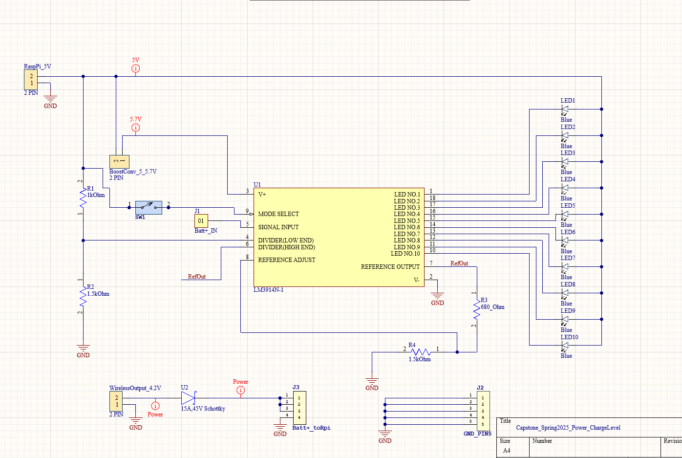
Power System
The system is powered by a 3.7V 5000mAh that is boosted up to 5V to power the Raspberry Pi. The LM3914 IC is used to display the charge level of the LiPo battery. 10 LEDs are used to show the charge level in the battery, each representing a voltage change of 0.12V. The range of this is controlled by a series of voltage dividers connected to our upper and lower voltage limit pins on the IC.
A Schottky diode is used to prevent the backflow of current into the wireless charger. When the cube on the wireless charger, it is charged as the system is powered by the battery. If the battery is removed, normal operation is able to be continued from the wireless charger alone. The battery is capable of powering the system for ~3 hours.
Key Components
| Component | Specifications | Purpose |
|---|---|---|
| Raspberry Pi 4b | Quad core Cortex-A72, 4GB LPDDR4-3200 SDRAM | Main control system, LED pattern generation, IR signal processing |
| WWS2812B IC RGB LEDs | Individual Addressable 5V, 50mA | Visual display elements |
| SC0949 Lens | 12MP, 8MM IR Lens | Lens mounted on the camera module |
| SC0870 Camera Module | IR, Raspberry Pi camera | Camera connected to the Pi with a ribbon cable |
| Pimoroni Zero LiPo Shim | TPS61232 Step-Up Boost Converter | Power management module for the Pi |
| Taidacent Wireless Charger | 5V 5A High Current 24V DC | Charges the battery and powers the block |
| IR Longpass Filter | 700nm visible light cut filter | Removes visible light from passing through to the camera |
| 755590 Li-Ion Polymer Battery | 3.7-5V, 5000mAh rechargable battery | Provides power to the block |